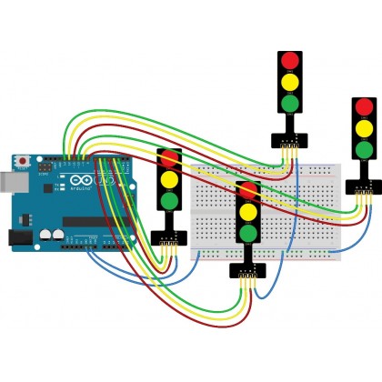

The project is a simple representation of traffic light controller and hence no other extra components are used. Since the project is a traffic light controller, the circuit consists of many LEDs (12 as a matter of fact) as we are implementing traffic lights at a 4 way intersection. (Foe Blue LED, the maximum current can be up to 30mA). The maximum current that can be allowed through these LEDs (Red, Yellow and Green in particular) is 20mA. LEDs: The LEDs used in the project are basic 5mm LEDs of Red, Yellow and Green colors. Arduino UNO will serve the purpose in this project to handle all the switching of the LEDs and controlling their timings.

The yellow LED will always glow for half of the time, the other red and green LEDs are glowing. Outputs are appropriately combined with diodes to on/off the particular LEDs. We have used PIN 3,2,4,7,10,1 ( outputs: Q0,Q1,Q2,Q3,Q4,Q5) of IC 4017 to derive the output to control the LEDs. Which then increments the counter by one, according to the Time period of the clock input. Output from IC 555 pin3 is input for the IC4017 Decade counter.

In case you are not familiar and comfortable with calculations, you can check this detailed article and online ic 555 calculator tool here, IC555 Calculator Online Tool IC555 Astable oscillator Calculator. The Time Period is the sum of Time High(T1) and Time Low(T0). => T1=0.694(R1+R2)*C, where T1 is Time for the Pulse to be high We have IC 555 here as the clock pulse generator, whose pulse high and low duration can be calculated and set by the formula below:
#Arduino traffic light with timer how to
You can read about the IC 555 in astable multivibrator and how to calculate the IC 555 clock pulse generators components according to the desired time, frequency, duty cycle, etc.

In case, if you are new you can sum-up from here ( IC555 Calculator Online Tool IC555 Astable oscillator Calculator) and ( IC 555 Delay Timer). We know about the IC 555 delay timers & clock circuits. Automatic traffic light controller circuit Components Let’s first start with the circuit, components, and working of our traffic light controller circuit. You can also make your own customized time circuit, by just selecting the R1, R2, and C2 by yourself and calculating the time by a formula. Although everything can be adjusted within the time range of selected components by just adjusting the potentiometer. Usually, the maximum time is 2.5 (or, you can customize easily according to your need) in all and the maximum time between each light change can be from 30 secs to 1 minute &30 secs. Here we are discussing a smart traffic light controller circuit whose time can be adjusted by a potentiometer and is also very customizable just by changing the value of some components.


 0 kommentar(er)
